
This project is a competition-winning design for a footbridge across the River Avon which not only serve connected the river banks and the other side, but also structurally independent of the river banks and unthreatening to the historical building on the other side of the river.
The form of this bridge is a Mobius Strip which follows the basic nurbs curve in three-dimensional space. Ordinary mobius strips are relative easier control geometries which based on the loft between a series of rotated section followed the rule whic h is perpendicular to a periodic nurbs curve. Each section rotated with equally angle and the whole rotation should be more than 180 degree.
So while modeling, there are two important difficulties to solve. The first problem is how to create the basic nurbs curve when all the control point is not in one plane and the curve itself is a non-logical curve. The second question is how to control the rotation of the sections since we need to provide a relative horizontal surface for people to walk on.
 |
| Add caption |
 |
| Add caption |
The Whole Modeling Process


 To the beginning, i decided to make additional loft in the gaps among the lofts. So i used list item node to select the final section of the previous loft and the first section of the loft behind. Then i can easily loft these section. However, in this way, the geometry will never be a smooth curved geometry since the kink appeared when the two loft connect without any rotation of the connected section. Or maybe i am able to control the two sections of the small connected loft with little rotation which showed difference between the two lofts which i wanted to connect.
 However, i decided to achieve my goal in a clever way. I used merge node to merge all the four list of the section, then i can create loft easily without any break.
Then we got the bridge expected.
 Then we can analysis this bridge. In order to simplifying the analysis process and limiting the bug, I exploded this Brep and use list item to choose only one surface to analysis.
 First, i did some curvature analyses in rhino.


 Then i did the gravity analysis using grasshopper. I only chose the lowest points in both left and right to be the anchor points.
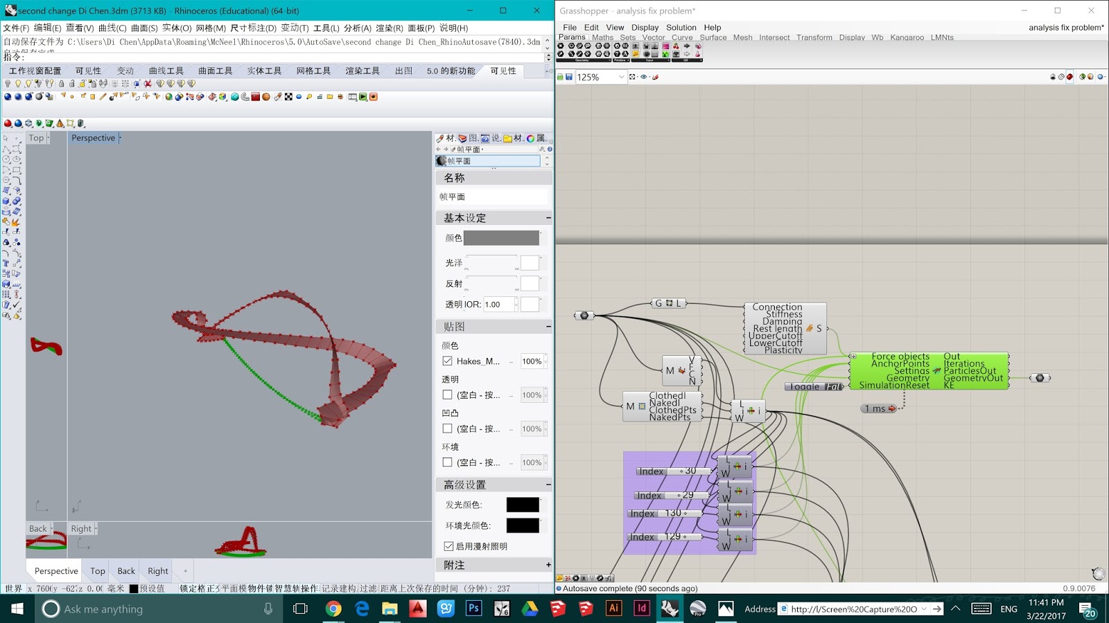 Since this is a curved geometry which is divided into lots of pieces automatically in grasshopper when i transform it into mesh, if i chose all the points on the edges to be the anchor point, nothing appeared when i reset kangaroo. This is because the anchor point is too much which meant this bridge is tooooooo stiff that it would never fall. So instead of selecting all edge points, i just chose the lowest four points.
Comments
Post a Comment